Command Quick Reference
| Command | Function | Example of use |
|---|---|---|
| C1 | Automatic Tool Changer (CNC #2 ONLY) | Chooses a new bit (1-9) from the Tool list. |
| C2 | Z-axis Calibration (CNC #1 ONLY) | Calibrate the Z-axis for the bit with the help of the Z-zero plate. |
| C3 | Home Calibration | Carriage will 'Home' itself to 0,0 |
| C5 | Spindle Warm-Up Sequence | Spindle will cycle from low, med, high to warm-up, Takes 6-Minutes. Only required for the first cut of the day. If others are using the CNC prior to you; this has already been done. |
| J2 | Dual-Axis Jog (X,Y) | Jogs the carriage by 2-axis, using the format X-axis then Y-axis Example: enter 'j2 12, 24' to send the carriage to 12" on the X-axis and 24" on the Y-axis |
| JX | JY | JZ | Single-Axis Jog (X, Y, OR Z) | Jogs the carriage by 1-axis, specify which axis by 'JX' or 'JY' or 'JZ' |
| Z2 | Sets temporary 'Home' position | Change the 0,0 reference point from the default corner to the current location of the carriage. |
| JH | Jog Home | Moves the carriage to the designated 'home' position from any point. |
FP | File Part Load | Opens a ShopBot.sbt file to run from the start. (default) |
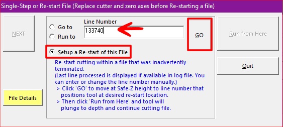
| FG | File Load in Goto/Line mode | Opens a ShopBot.sbt file to run from a specified line. For use when restarting a failed/paused job part way through. (additional troubleshooting on last page) |
| TR | RPM Spindle Controller | When this window is open the spindle will be able to read the RPM from your file. |
Input Quick Reference
| Input | Function | Example of use |
|---|---|---|
| 1 | Aluminum Z-plate | Only on CNC 1; for manual Z-axis calibration |
| 2 | X-axis Proxy | Proximity sensor for X-axis |
| 3 | Y-axis Proxy | Proximity sensor for Y-axis |
| 4 | Emergency Stop Button | Big red Emergency STOP button located above the workstation |
| 5 | ATC Z-plate | Only on CNC 2; for automatic tool changer |
| 6 | Z-zero plate | Only on CNC 1; Fixed Z-axis calibration plate |
ShopBot CNC Process
- Double-check that the bit you are using is the exact type of bit mentioned in the CNC Templates page. If you don’t use the right bit, your part will not come out correctly.
- The ShopBot CNC will perform ANY command given without question. It is important that YOU question every command to ensure no damage is done to the machine or to the surrounding shop patrons.
Part 1: Machine Calibration
- Sign-in to the CNC Workstation using your EID credentials
- Clear the CNC bed off to ensure no collisions occur
- Ensure that the brush is magnetically attached to the end of the CNC router
- Ensure that the dust collection gate is open and clear of obstructions; feel for airflow to ensure dust collection system is working

- Turn on the ShopBot using the red switch on the control box

Press the blue, reset button (middle) on the ShopBot pendant located at the workstation

- Check the fan above the spindle and ensure that it is powered on

- On the workstation, launch the ShopBot 3 program from the desktop or search 'sb3' on the start menu

Next, perform the homing calibration; this process differs depending on which machine you're on.
CNC 1 CNC 2 - Ask a Build Lab staff member to install your router bit
- Enter command 'C3'
- ShopBot will home in the X-axis and Y-axis
- Enter command 'C2'
- ShopBot will home in the Z-axis
- ShopBot is now homed
- Enter command 'C3'
- ShopBot will home in the X-axis, Y-axis and Z-axis automatically
- ShopBot is now homed
- Enter command 'JZ 4' then 'JX 80' to jog the spindle to a safe location in preparation for loading your stock material
- Enter command 'TR' to open the auto RPM Spindle Control window

Part 2: Spindle Warm Up Sequence
The operator is responsible for ensuring that the warm up sequence has been ran at least once that day. If the sequence has already been ran, you may skip to 'Part 3: Loading Stock Material'
- The ShopBot CNC MUST go through the spindle warm up sequence to prevent damage to the spindle.
This process takes 9 minutes and only needs to be done once per day.- Enter command 'C5' to start the spindle calibration routine
- A dialogue box will pop up asking you to start the router/spindle with 'start' button; DO NOTHING and proceed to next step
Press the green, start button (right) on the ShopBot pendant located at the workstation to turn the spindle on
- Verify VISUALLY that the bit is now rotating in the spindle
- Click 'Yes/OK' to start the spindle warm up sequence

- Once the operation is complete, proceed to the next step
Part 3: Loading Stock Material
Stock material should be at least 20" x 20" or larger in size for the vacuum table to perform correctly.
Smaller footprints will require an additional plywood sheet be mounted beneath your stock to create a larger surface space for the vacuum table.
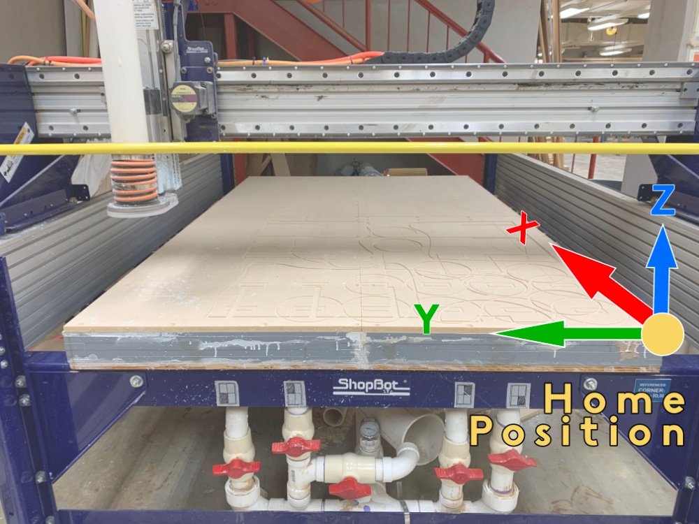
- Place your stock material on the home position 0,0 reference point
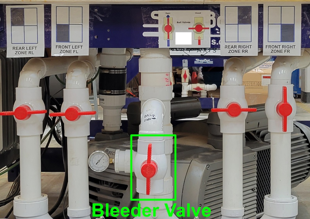
- Ensure that the bleeder valve is OPEN to relieve pressure from the vacuum system
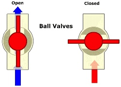
- Open/Close the appropriate zones for your stock material, ensuring uncovered zones are turned off at the ball valve to provide the best vacuum hold down to your stock.

- Turn on the vacuum table with the red switch on the blower control box mounted to the wall

- Ensure that 1 or more zones are open, then close the bleeder valve; failure to perform this action correctly will result in damage to the blower motor

- Give your stock material a solid push to ensure that it is held down tight with the vacuum table suction
- Use the provided airflow redirect sheets stored against the wall to block off and redirect airflow to your stock

- Use the provided airflow redirect sheets stored against the wall to block off and redirect airflow to your stock
- If your stock material budges after the last step, you should redo the steps for 'Part 3: Loading Stock Material'
Part 4: Running a Job
Download your ShopBot job file or transfer it from a USB drive and save the file to the desktop to ensure that no errors occur during the operation.
- Ensure that your file is saved locally to the desktop
- Enter command 'FP' to load your file
- A yellow notepad window will appear, you can ignore this and click the green 'START' button on screen

- Pay extra close attention to what the dialog boxes tell you on these next steps
- If a box pops up asking if the right tool is in the spindle; verify that it is and click 'Yes/OK'
If a box pops up asking if you have zeroed the bit; click 'Yes/OK'
If a box pops up asking you to start the router/spindle with 'start' button; DO NOTHING and proceed to next step
Press the green, start button (right) on the ShopBot pendant located at the workstation to turn the spindle on
- Verify VISUALLY that the bit is now rotating in the spindle
- Once the spindle is on and spinning you're ready to cut!
- Click 'Yes/OK' while keeping your hand near the red EMERGENCY STOP button while the operation starts
- Your job will now start!
Keep an eye on the cuts to ensure they look accurate to your original file and the simulation. If you notice something, it is best hit the EMERGENCY STOP and review your file and or calibration steps.
Shutdown & Cleanup Process
Jog the spindle out of the way if it is blocking you from retrieving your part 'JZ 4' then 'JX 60'
Open the bleeder valve and turn off the blower motor using the blower control box switch to release your cut part from the CNC bed
Depending on which machine you are using...
CNC 1 CNC 2 - Asked a Build Lab staff member to retrieve your bit from the spindle
- Jog the spindle to the resting home position by entering command 'J2 5,5' then place the white PVC tube under the Tool. 5, 5 is outlined on the table with a blue circle.
If no one is in the queue to use the machine after you
Turn off the Vacuum Table system
Turn off the ShopBot control box
- Close the dust collection vent
Log off of the CNC workstation
Use the shop vac, broom and dustpan to cleanup the CNC bed and the surrounding areas
Troubleshooting
Did an error or sudden stop occur during your job? did you have to press the emergency stop? Try some of these solutions!
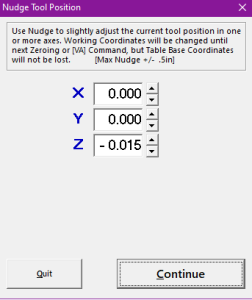
Your print is not cutting through to the desired depth; this can be caused by a file issue, tool tip calibration or a worn table surface. If you experience any of these issues please send an email to soatechdesk@utexas.edu to ensure that a staff member is aware of machine or table damage. Proceed with caution when using the NUDGE command. Any damage to the spoil board should be reported so that it may be addressed prior to the next CNC user. The goal is to cut 100% through your material and not to go deeper than 1/32 of an inch into the spoil board. Proceed to CNC Troubleshooting | Router | Resuming a stopped job if you recorded the Line # that your job stopped on.Problem
Solution
This guide is intended to be used to start a job that was inadvertently terminated. If you receive a '-- Unexpected Output Fault ! --' error, make sure to note down the line number in the 'Current Line' box.Problem
A Job may stop or fault for a variety of reasons. The '-- Unexpected Output Fault ! --' error is caused by a miss-step in communications from the workstation to the Shoptbot controls.Solution