Step 1: Open the model and save as a .ply file
I: Open Meshlab
II: Press File → Import Mesh in the menu bar and select your .stl file from the appropriate folder.
III: Press File → Export Mesh As… in the menu bar and save the model as a .ply file.
IV: Close Meshlab, then reopen it. This time, press File → Import Mesh, and choose the newly saved .ply file. Work only on .ply files, and back up your work periodically by saving new versions of the model.
Step 2: Adjust model axis – the axis acts as the point of rotation for the model. It rarely falls within the body of the specimen by default, making manipulation of the model difficult.
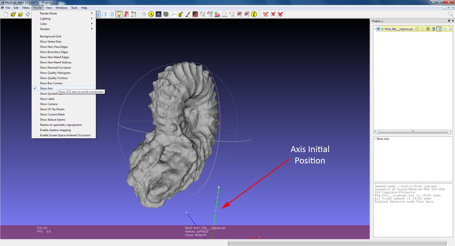
I: Press Render → Show Axis in the menu bar at the top of the page – this allows you to visualize the X, Y, and Z axes.
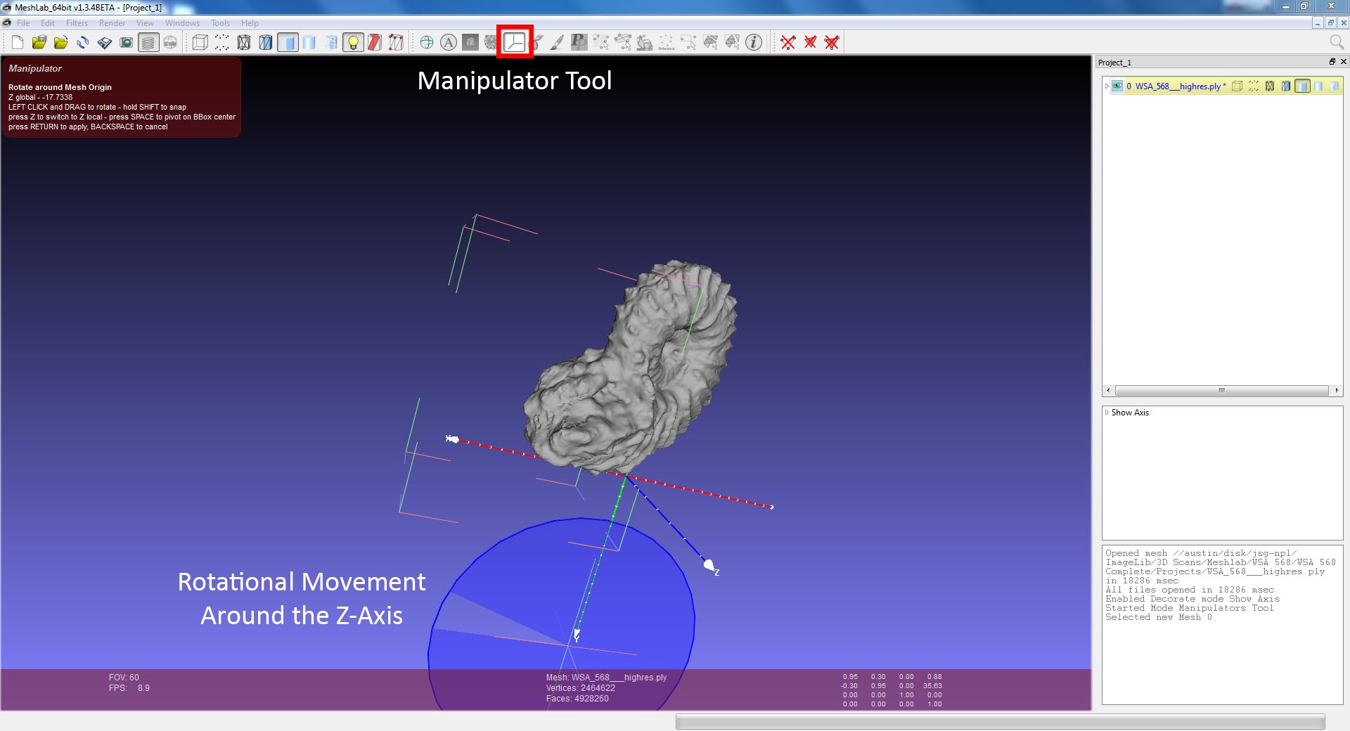
II: Move the model until the axis falls within the model, with the X, Y, and Z axes pointing the direction you want. Press the Manipulators Tool button in the toolbar near the top of the page, or by going to Edit → Manipulators Tool in the menu bar. When the model is in this mode, a colored box will appear around the specimen. To manipulate the model and axis, use the following commands. To leave this mode, press the button again.
- Esc – Toggle between manipulator movement (moves just the model relative to the axis) and normal movement (moves both the model and the axis together). If you’re in normal movement, both a box and axial circles will surround your model. In manipulator movement, only a box will be present. These modes have different commands, (indicated below).
- T + (X, Y, or Z) – Allows translational movement of the model along the specified axis. The axis selected (X, Y, or Z) will become highlighted. Translation of the model with then be constrained along that axis. Manipulator movement only.
- R + (X, Y, or Z) – Allows rotational movement around the specified axis. A circle will appear around the axis selected. Rotation of the model will be constrained around that axis. Manipulator movement only.
- Enter – Save applied movement changes for each movement. After each rotational or translational movement, you have to press Enter. Otherwise, that movement will not be saved, and the model will revert to its prior position. Manipulator movement only.
- Ctrl (Hold) – Press Ctrl while moving the model with the mouse to move the model laterally. Normal movement only.
- Shift (Hold) – Press shift while moving the model with the mouse to increase and decrease the size of the model. Normal movement only.
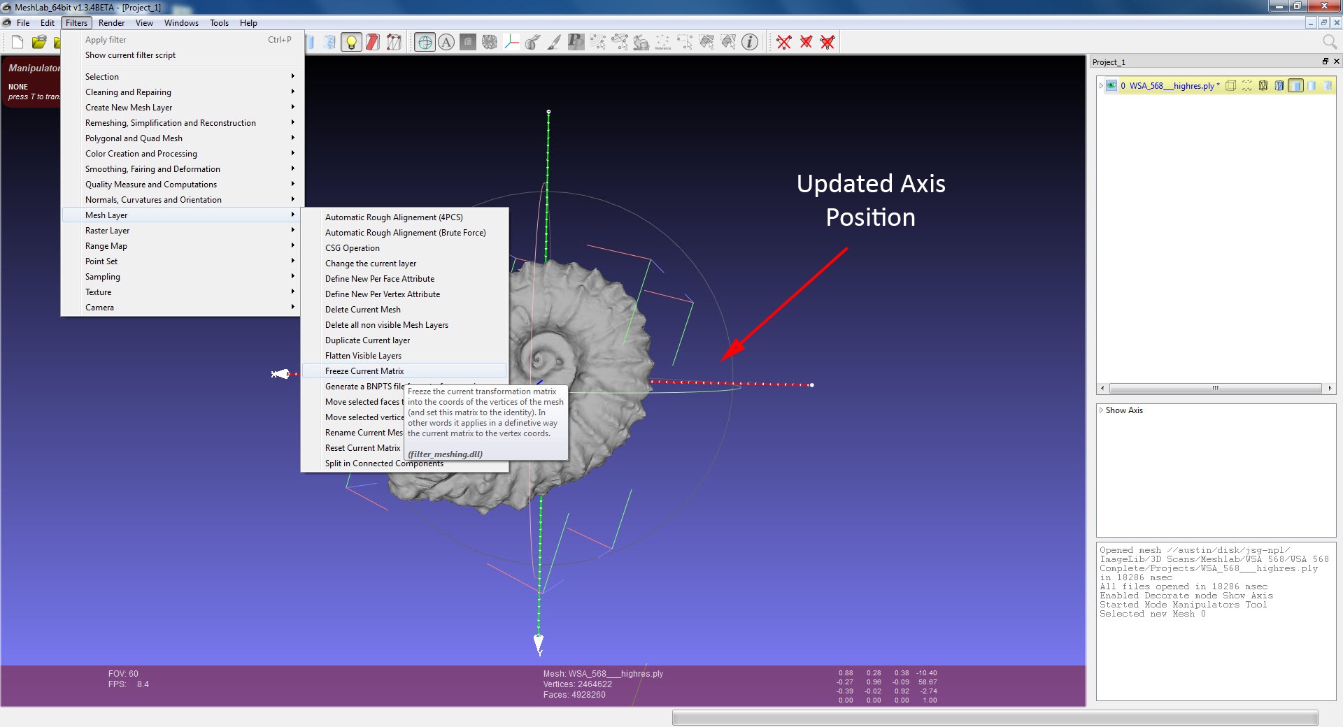
III: Freeze the axis position – Press Filters → Mesh Layer Freeze Current Matrix in the menu bar. Until you do this, both the current position of the axis, as well as the original position of the axis will be visible. Performing this step will permanently adjust the axis into the new position.
IV: Press File → Export Mesh As… to save a new version of the model as a .ply file. The axial information is stored within the model, not the project. Saving the project alone will not retain your change in axis position, so be sure to use this model as you continue working.
Step 3: Take pictures for overlay
I: Photograph the specimen from many different angles in Helicon Remote.
- Be sure every crevice and cranny is photographed.
- Ensure consistent lighting between images.
- Once you begin overlaying images, you may have to return to this step to take additional photographs.
II: White balance and adjust contrast and color settings in Photoshop as needed to ensure all images are roughly the same color tone and contrast.
- It helps to clip the specimen out from the rest of the image and color the backgrounds of all the images a single, consistent color. Generally, a color similar to the overall color of the specimen is useful, as it helps cover up color discrepancies in the overlay.
III: Save the images in .jpg format. Other image file formats are incompatible with MeshLab.
Step 4: Import the images into MeshLab
I: Press File → Import Raster from the menu bar
II: Select the .jpg images you’re using in your overlay.
- Not every image needs to be uploaded at once; additional images can be uploaded later
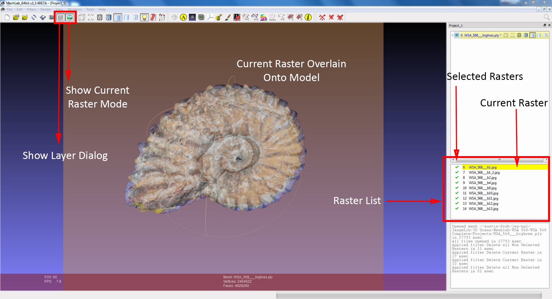
III: Images should appear in a list on the right hand side of the screen. If they do not, press the Show Layer Dialog button in the tool bar.
- Oftentimes when opening a saved project, the imported rasters will not automatically appear, despite being saved. Just press the Show Layer Dialog button to display them.
IV: Press File → Save Project to save your work. Do this periodically and create backups of your work at each step.
Step 5: Overlay images onto the model
I: Select the image you wish to overlay from the list of imported rasters.
- The raster highlighted in yellow is the current raster
II: Press the Show Current Raster Mode button in the tool bar to display the selected image and the model.
- Alternatively, press View → Show Current Raster Mode from the menu bar
III: Press Ctrl + H to orient the camera to the model.
- The model will likely not show up on the screen initially, as the raster camera hasn’t been set.
- This command can be used in any screen to direct the camera at the model, regardless of its position
IV: Manually align the image to the model
- Controls for moving the model are the same, but scrolling with the mouse adjusts the opacity of the image
- Get the model as aligned as closely as possible free-hand before moving on to the next step, (you won’t get it perfect).
V: Press Filters → Camera Image Alignment: Mutual Information to precisely align the image and model
- In submenu, make sure settings are set to:
- Rendering Mode: Combined
- Starting Shot: Current Trackball
- Estimate Focal Length: [unchecked]
- Fine alignment: [checked]
- Max Iterations: 100
- Tolerance: 0.1
- Expected Variance: variable (see below)
- Background Weight: 2
- (These can be adjusted, but it’s best to leave all of them alone except for Expected Variance)
- Adjust Expected Variance based on how close your manual alignment of the model is to the image.
- The default is 2. It’s best not to go higher than 2, as the larger the number, the less accurate the alignment will be
- For minor alignment, values of 1 or 0.5 work well
- If your model is aligned where you want it, and you don’t want it to move, adjust the expected variance to 0
- Press Get Shot, then press Apply. The model will automatically adjust to match up with the current image.
- You must press Get Shot first, otherwise the adjusted settings will not be applied to the alignment. There is no feedback to indicate you’ve pressed Get Shot, but if you pressed it, the changes will be applied.
- Repeat the above steps as necessary to ensure ideal alignment. This step can be done multiple times. Once the model stops moving relative to the image, the program has achieved its closest alignment.
- If the program is doing a poor job of automatically adjusting the model, readjust the model manually and at a slightly different angle, or lessen the Expected Variance.
VI: Repeat the previous steps to apply all of the images to the model.
VII: Press Render → Rasters-to-geometry reprojection in the menu bar to see how the model looks with the overlay applied.
- Check for patches on the model missing texture, or misaligned. Take additional pictures and repeat previous steps as needed to cover up discrepancies.
- It’s best not to leave this option on constantly, as it slows down the program. Turn it on only when you need to check how the overlay looks.
VIII: Save the Project
Step 6: Apply the images to the Model surface
I: Press Filters → Cleaning and Repairing → Select non Manifold Edges in the menu bar to select all edges where more than two faces are incident.
- In the sub-menu, press Apply to select the edges. Don’t adjust the other options.
- You can press Render → Show non Manifold Edges in the menu bar to see the number of edges selected. This is not a necessary step.
II: Press the Delete Selected Vertices button in the tool bar to delete the faces selected in the previous step
- Alternatively, press Filter → Cleaning and Repairing → Delete Selected Vertices in the menu bar
III: Press Filters → Texture Parameterization + texturing from registered rasters in the menu bar to apply the images to the model
- This will produce a .png texture file in the same folder as the .ply file you’re working on
- At this step, the model and texture are still disassociated. Reopening the project may require you to repeat this step to reapply the images to the model.
- Use this step to double-check and make sure the applied texture is accurate. Repeat previous steps as necessary to ensure the texture is accurate.
- If the texture looks wrong, the problem rasters can be deleted, and this step can be repeated. Each time this step is performed, the texture will be updated with your current list of rasters.
- Only perform the next step when you’re sure the texture is exactly how you want it.
IV: Press Filters → Color Creation and Processing → Transfer Color: Texture to Vertex in the menu bar to apply the texture overlay to the geometry of the model
- This step takes the overlay from the previous step and colorizes each model vertex appropriately. This links the geometry of the model with the texture overlay, ensuring the texture remains with the model anywhere it goes, allowing it to be uploaded.
- If the color of the model appears unusually dark or saturated, it is likely because the program is displaying both the vertex color and the color overlay from Step III simultaneously. Press the Texture button in the tool bar to toggle the texture overlay off, allowing you to just see the vertex color. This is the color that will remain with the model.
V: Press File → Export Mesh As… in the menu bar and save the final .ply model
- Save a backup of the project as well


