...
- Run VCarve Pro V8 (Note: VCarve Pro V7 - Shopbot Edition will NOT work)
- Choose File->Open and select the .dxf file that contains the lines you want to cut (best practices for .dxf files listed below)
- The .dxf file should be AutoCAD 2000 DXF if exporting from AutoCAD/Revit, or AutoCAD Exchange Drawing if exporting from Rhino
- The .dxf file should contain a material layer showing the extents of the material (usually a rectangle). The material should be oriented to correspond to the physical machine, which is 96" in x, and 48" in y.
- The lower left corner of the the material rectangle should be at 0,0 in the coordinate system.
- The .dxf file should only contain the material layer and layers that you wish to cut, it is recommended to delete other dimensions, drawings or objects from the final file.
- The .dxf file should contain different layers to control (1) cut order and (2) depth of cut. Do all etching first, then cut out nested objects interior to exterior.
- Although closed shapes are not required for the CNC Knife, using PEdit, Fillet and Overkill in AutoCAD to make clean closed shapes can help insure efficient and effective files.
- Enter the Job Setup Parameters

- (1) Job Size - if you follow the material layer recommendations in best practices, these numbers should be filled in automatically and correctly - you should double check and verify these numbers and make sure that x does not exceed 96" and y does not exceed 48".
- (2) Material Thickness - If you are doing all cut-through cuts on the CNC knife, you can use estimated material thickness (please estimate within 1/16th"). If, however, you are using scoring or etching and need accurate depth, you will need to use caliper measured thickness and be extra precise when zeroing the z axis in the machine procedure.
- (3) Z Zero - Z should be zeroed to the bed (bottom of material) for all CNC knife operations and files.
- (4) XY Datum - The origin should be in the lower left corner of the file - this matches the .dxf file best practice.
- (5) Units - Make sure your units here match the units you used in your design file/software.
- Click 'OK'
- Preparing for Toolpath Creation

- (1) Click the 'Pushpin' in the upper right to expose and lock the 'Toolpaths' Toolbar.
- (2) Click the 'Layers' Tab to expose the list of layers in your file.
- (3) Turn off (by clicking the light bulb) the visibility of all of the layers in your drawing except the first one you want to cut ('first cut' in this example).
- (4) Select the first layer you want to cut ('first cut' in this example), the layer name should be bold and black.
- Process Layer
- Select All Objects on the Current Layer - Click in the white drawing space & hit Ctrl-A on your keyboard or use the mouse to draw a fence around all the visible objects. They should all turn to pink-dotted lines.
- Select the 'Profile Toolpath' button from the 'Toolpath Operations' pallette (it is the first one - upper left)
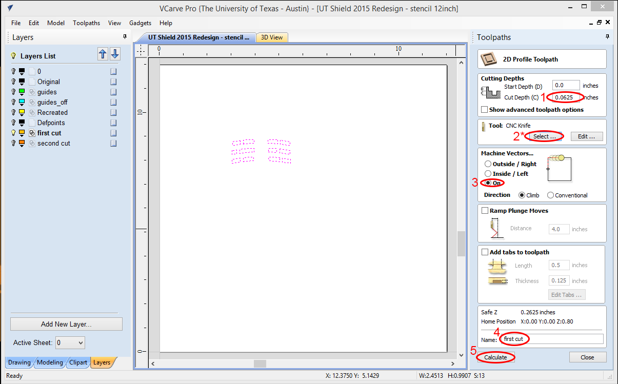
- (1) Set the cut depth, for cut throughs this should be equal to your material thickness (hint: if you want your material thickness to go in this box you can type "t=", if you want half material thickness you can type t/2=, etc.)
- (2) Select and Verify the CNC Knife settings (See bullet 6 below)
- (3) For CNC Knife, all cuts should be ON the line.
- (4) Enter a toolpath name - we suggest using the same name as your drawing layer to avoid confusion and make 1:1 verification easier.
- (5) Click 'Calculate; - this applies the parameters you just entered to the geometries you selected and does the math that tells the CNC how and where to move.
- Tool Database - CNC Knife Tool Settings (*You only need to do this for your first layer - once the values are set, they will stay the same for the rest of your session.)
 The default values - appropriate for MOST situations.
- (1) Pass Depth - This parameter tells the CNC how deep it can cut at one time. So when the material is thicker than the cut depth, the machine will make more that one pass to cut through the material. Your pass depth should NEVER be deeper than the cut length of your knife and your material thickness should never be greater than the blade's depth. For thin materials (<0.25") you would usually leave this setting at 0.25 - unless cutting a hard/tough material where you need more shallow passes. If you are cutting thicker materials with longer knife blades you may choose to use a deeper pass depth, in general deeper path depths increase the risk of breaking a knife blade and decrease the amount of time it takes to process a job.
- (2) Feed & Plunge Rates - 2.5 inches/sec is the general recommended cut speed for most CNC Knife work. Some hard/tough materials may require slower speeds, some very soft/fragile materials could be cut at higher speeds. Experimenting with speeds, generally, increases your risk of breaking a blade. 6 inches/sec is the top recommended cut speed for soft materials.
- (3) Tool Number - This MUST BE SET TO 1 so that the software file matches the physical setup of the CNC Knife.
- After you Calculate - preview your results, then go to your next layer:

- (1) The blue lines represent the knife cutting the material, the red lines represent the knife moving above the material without cutting. Click the preview button and the computer will generate a rendering of the cuts you have programmed following the blue lines. If you are happy with the results, click close (2) and then double click the toolpath name to reopen and edit your toolpath parameters or select different geometries. If you are happy with the results, click 'close' (2), and proceed to the next step.
- (3) Go back to the 'drawing' tab (i.e. the tab with the name of your file).
- (4) If you have only one layer or have just processed your last layer, skip to step 8. Otherwise, turn off the layer you just processed (lightbulb) and turn on and select the next layer you want to process. Once you have the next layer selected go to Step 5 and continue.
- Verify Toolpaths
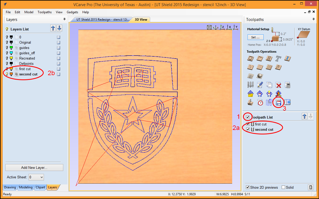
- (1) Select the checkbox next to the 'Toolpath List' - this will make all of your Toolpaths visible.
- (2a & 2b) Verify that you have a Toolpath created for each layer in your original file that was supposed to get cut.
- (3) Click the 'Save Toolpath' button.
- Save Toolpath

- (1) Select the Output all visible toolpaths checkbox.
- (2) Select the AXYZ A2MC (*.nc) Post Processor in inches or mm to match your file.
- (3) Verify that you want to cut all the Toolpaths you have selected and that they are in the correct order. If you want to skip or omit a toolpath, just uncheck the box next to it. If you need to change the order, select a toolpath and use the blue arrows to move it up or down in the list. The list will cut from top to bottom as shown.
- (4) Save the Toolpaths - click on this button and then select a name and save location for your .nc file. This is the file that tells the CNC Knife what to do. This file ultimately needs to end up on a memory stick or external hard drive (must be FAT 32 formatted) inside a 'Jobs' subdirectory at the root of the drive.
- (5) File->Save - this saves a .crv file, which is the file that you can edit in VCarve Pro later to make additional CNC (.nc) files or to modify toolpaths.
...