Page History
First launch the 4B Salvo for the 4E control room setup and turn on both power switches | |
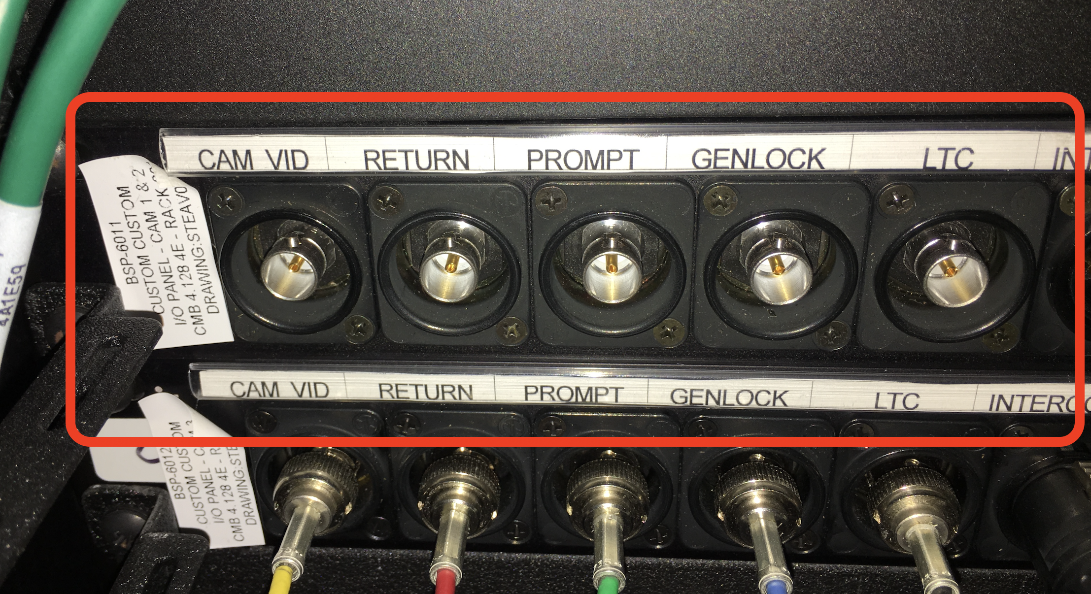
In 4E open the cabinet that has the camera BNC connectors |
|
Disconnect the 5 BNC camera outputs Cam VID RETURN PROMPT Genlock LTC Pull the cables out of the Rack at the bottom hole |
|
Then roll the camera with the teleprompter to the studio 4B |
|
This will go into 4B camera position 2. In Studio 4B and open the Patch Bay metal cabinet Run the cables under the cabinet and up to the patch bay |
|
| TURN off the Alarm Keypad | |
| Keep in mind that 4B cameras are on the loop alarm, which runs through the 'Teleprompter' BNC connection. So you will disconnect camera 2 from the 4B rack, make sure the alarm is off and put a BNC return on the 'Teleprompter' port, then connect the rest of the cables on the camera 2 input and returns. |
|
and patch a BNC cable out of CER TIE 2 (The Picture shows Tie 1, but that should be Tie 2) (Control Room Tie Line) to the Decimator |
|
Patch the other end of the BNC into the Decimator SDI input Patch an HDMI cable out of the Decimator to the input of the Teleprompter monitor on the camera |  |
Patch the HDMI out of the Decimator to the Teleprompter HDMI input |
|
This is the correct settings on the Decimator software that is on our windows “tuning” laptop.
The software is also downloadable free |
|
| General HDMI Setup notes |
|
To flip the image go to Scaling> Check Horizontal Flip Enable |
|
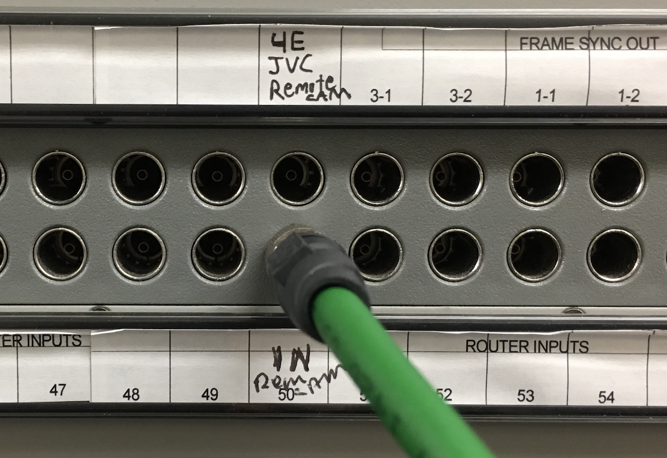
Go to the machine room behind the proctor desk and make sure the patching is setup like this (the Green cable is from another setup) |  |
Green Cable = Out LAB B Tie 1 (this is for another setup, the handheld 4th camera setup return to the switcher) Yellow Cable = IN LAB B Tie 2 Red Cable = Out LAB E Tie 1 |
|
| Green Cable = In REM CAM (Another setup) |
|
Yellow Cable = Out SPARE DA2 OUT 1 Red Cable = IN SPARE DA 2 IN This part is critical to get the signal to regenerate from 4E to the machine room to 4B. Otherwise a direct patch would be too long for the signal. |
|
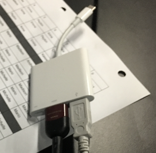
Go back to 4E studio where the laptop is connected Next connect the Laptop or computer to HDMI Ex: USB-C to HDMI adapter |
|
Connect the other end of the HDMI cable to the HDMI to SDI adapter ex: here using Adaptec brand HDMI to SDI converter |
|
There is a small knob on this device that you need to use a “tweeker” to turn the knob so that the settings are 1080 5994 - In our case we had it set to 1 |  |
Connect the SDI output BNC out of the Adaptec HDMI to SDI converter to the 4E metal patch bay Rack into CER TIE 1 |
|
Audio connect a mini female to mini male audio cable to the IPOD input on the Wheatstone Connect the other end to the laptop or computer headphone out.
|  |
Set the 4B preset and put down the 4B magnetic label strip Turn up the IPOD input on the Wheatstone |  |
Next connect the SDI PROGRAM out to the Blackmagic Design Webpresenter Need another BNC cable locate the Brighteye in the rack and go to the back of the A/V Rack |  |
Unplug the OUT 1 and use a spare BNC cable to attach to the SDI out 1 to plug in to the Blackmagic Design Web Presenter |  |
to plug in to the Blackmagic Design Web Presenter |  |
Should see what is on the switcher on the blackmagic Web Presenter Check audio too Make sure the client's laptop has the Blackmagic Webpresenter as the camera and microphone inputs to hear the production audio and video. |  |


...
Overview
Content Tools