What you are about to read is a foundational document created by me, Noah Hickman, the Longhorn Racing Solar Frame Subsystem Lead for the 2023-2024 competition season. I have chosen to create this document to make a referenceable database for any new and future frame subsystem members. Though I made this documentation purely off my knowledge of solar car chassis building, this is a universal document that includes useful information for chassis design in general, which means any and every team, LHR Combustion, Electric, Solar, or even teams beyond UT Austin can hopefully utilize this document. I hope for this document to aid in the design, procurement, and manufacture of any and every piece of a competition car chassis.
This document or rather my experiences and knowledge gained from my time in LHR is not accurately portrayed or represented without acknowledging those who helped me along the way. From Solar’s team captain, to chief engineer and mechanical lead, as well as members and leads of both the Combustion and Electric team, I cannot thank those enough for the impact they have had on my own development as an engineer, and therefore the creation of this document and information therein.
Goals of the Frame Subsystem (subject to change):
- Take in hardpoint and design specifications from accompanying mechanical/electrical teams, and with said specifications, design a basic tubular (hopefully monocoque soon) frame to support those needs
- To meet the required load cases, design cross-bracing structures to satisfy roll-cage and occupant cell load cases, maintain 1/1.1+ FOS, and minimize stress and displacement of the tubes
- Simulate the frame using Ansys Mechanical (or FEA software in general) to validate the frame design and ensure it meets the ASC regulation
- Design and fabricate a frame jig, to plan out and maintain the structure during welding and construction
- Send out the finalized design to VR3 for mitering/tube-cutting, which includes drafting proper documentation like BOM, frame/tab drawings, and .sldprt files
- Weld the frame with the use of TIG welding principles and frame jig to properly hold the tubing in place
TLDR: build the frame and build it right 🫡
Foundational Documentation/Good Reads:
How To Build a Roll Cage - Ultimate Roll Cage Design Guide | Rogue Fabrication
Engineering A Lighter Chassis, Part 1 — DesignJudges.com
Tube Frame Analysis — DesignJudges.com
Design Of Strong, Stiff, And Light Structures And Joints — DesignJudges.com
These are all links to designjudges.com, which mainly focuses on FSAE guides, but are good general knowledge bases for frame design as a whole.
The entire “To Win” series by Carroll Smith is a great series written on motorsport racing and race car development as a whole. These are great reads as a whole if you like cars, motorsport, and automotive engineering in general.
https://drive.google.com/file/d/1q_pesz72ODhyHq1LT2QjQDi1M0DjC1mY/view?usp=drive_web
https://drive.google.com/file/d/1y6qGfDwpUNMxRk7VEfI5V7Ze6QSK71Fe/view?usp=drive_web
https://drive.google.com/file/d/1HtL0eSj_88jn9xyBph12DsSvQrAZXAhJ/view?usp=drive_web
https://drive.google.com/file/d/1o7v3r8eP3M2TiCM4WBweFN1Z2fyij8eQ/view?usp=drive_web
Necessary Statics/Solids/Materials/Structural Knowledge
To build an effective frame, one must be knowledgeable in the realms of primarily Statics, Materials, and Solids, as well as knowing the optimal ways to build structures as a whole.
DISCLAIMER: I never completed any of these classes upon first drafting this work, so here’s the quick and dirty, cut-and-dry, condensed version of what you will need to know 👍
Statics
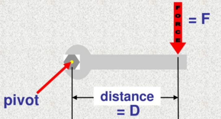
Pictured here is an explanation of moment
Firstly, tubes in a frame will experience various forces and moments when analyzing the load case requirements. (see the ASC regulations)
- Force → load applied at a point, causes stress (over an area), displacement, work, etc.
- Moment → measure of a force times a perpendicular distance from a point (I.e. tendency of a force to rotate around an axis of an arbitrary point)
Takeaways from this → We build a frame to take on different forces and moments, and furthermore, the things that they cause
What happens to a tube when a load case is applied?


Inside each beam, internal forces are present, which can cause different effects (i.e. compression → buckling, shear force→ shearing, bending moment → bending stress, etc.)
Axial Forces
- Axial forces (forces parallel to the center axis of the tube) can cause compression or tension in a tube, which can essentially be broken down into squeezing or stretching a tube
- Too much of either tension or compression can lead to either buckling or plastic deformation (see picture below/will talk about later)
- Tubes are the most resistant to axial forces as compared to shear forces or bending moments
- Buckling is more common in longer, less stiff tubes (I.e. shorter, stiffer tubing → less chance of buckling)

Shear Forces
- Shear forces (forces perpendicular to the center axis of the tube) can cause the shearing of a tube
- Think of it as a cutting force, like scissors cutting paper, a force perpendicular to the tube can sort of “cut” the tube in half
- Tubes are not as resistant to shear forces, as all the force has to do is overcome the wall thickness of a tube to shear it (as opposed to the entire length of a tube with Axial forces)
Bending Moments
- Bending moments (forces that cause a rotation around a fixed point, causing bending) can cause bending stress (this is the root of most all problems in frame design)
- Bending moments have a lot to do with load pathing (i.e. if your tubing and therefore your load path is a straight line, no bending moment is caused (forces are only axial), but as soon as you introduce an angled path, bending moments are caused)

Supports will come in later when you take Statics/are introduced to Ansys (FEA).
- All that matters is that different types of supports resist different types of forces/moments, which you can use to solve/isolate forces and understand the reactions happening in a system
Materials
Every material is made up of a crystal structure (crystal defects, a unique organization of atoms, etc.) which leads to materials with unique/different properties (i.e. this is how you get alloys, a mixture of chemical elements with at least one metal)
- You can look more into this on your own, but essentially, we pick a tube material based on its makeup and its properties (weight, density, yield strength, Young’s modulus, etc.)
- We have previously used 6361 aluminum alloy and 4130 chromoly steel.
What happens to a tube when a load case is applied?
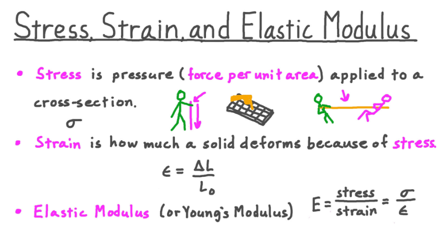

This is a stress-strain curve. All you need to know is:
- The graph has stress on the y-axis, strain on the x-axis
- The elastic region is where the material can have stress applied (elastic deformation) and the process is reversible (the material can go back to its original length)
- The elastic line on the graph is linear because the stiffness of material in this region is like a spring (everything in every situation is like a spring from here on out, remember this lmao)
- The plastic region is where the material has stress applied (plastic deformation) and the stress overcomes the energy required to rupture bonds, which is an irreversible process
- Two Important things: Yield Strength and Ultimate Strength
- Yield strength is the maximum stress a material can absorb before plastically deforming
- Ultimate strength is the maximum stress a material can absorb before fracturing (breaking)
- I’ll talk about this later on in the guide when we get to welding, but essentially, just know that we mainly design things around the yield/ultimate strength.
- Lastly, the Factor of Safety, at least in our case is measured with the yield strength of the material, as well as the max von Mises equivalent stress from the given simulation/reaction (the equation is Max eq stress/yield strength)
- This indicates when a part can fail
- FOS of 1 means the current simulation/reaction will begin to fail at 1 times the max equivalent stress, 2 means the structure begins to fail at 2 times the max equivalent stress, etc.
- FOS of 1 is the absolute bare minimum a structure should have before it is deemed manufacturable, but some parts of the frame must have a 1.1 minimum, due to high safety goals/concerns
Solids
What happens to a tube when a load case is applied?

There are 4 main types of stresses each tube will encounter. Those include:
- Normal Stress: Stress that acts perpendicular to the cross-section of interest (compression, tension, or rather axial force)]
- Shear Stress: Stress that acts tangential (parallel) to the cross-section of interest (like a cutting force)
- A common application of this is with bearing stress on a bolt, which leads to shearing
- Torsional Stress: A shear stress that is caused by a moment about the longitudinal axis of the tube (think of a twisting force)
- Bending Stress (THIS IS THE BAD ONE): Stress caused by a moment that has tension and compressive stress at each end (think of the cantilever beam problem below
- Also, bending stress is related to moment of inertia (you’ll learn this in Physics I hopefully, but it is basically related to a tube’s stiffness/inertia/resistance to movement)


Some Necessary Basic Structural Knowledge
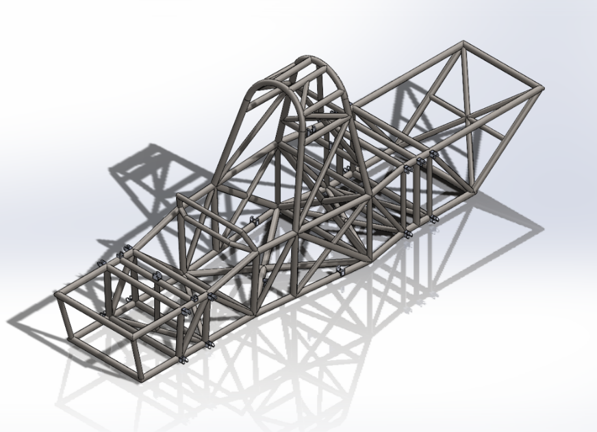
Triangles - Triangles are the most stable simple geometric structure. Without triangulation, squares have no lateral support. Triangulate everything you can. This principle should be applied as much as possible to a chassis or cage design. Every tube should be one leg of a triangle whenever possible. This is especially true with the primary structural tubes.
Bends - Avoid bends. The strength of a roll cage is based on compression and tension within the structure. Bending reduces both no matter where you do it. Some are unavoidable in a design but they should be minimized. A straight line is more rigid than a curved one. However, it's not always practical to have your roll bar tubes run in a straight line. Bending the tube results in a reduction in overall strength. If you have to use a bend, add bracing to compensate for the bends. Bends should never be mid-span, or unsupported. The apex of a bend should be a node point or junction for at least one other tube and gusseted unless several tubes meet at the node.
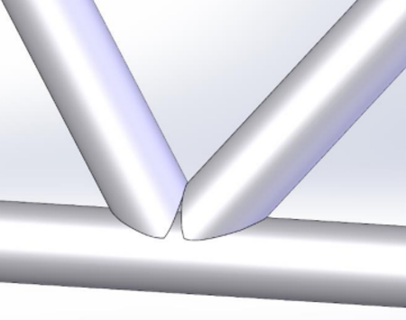
T-Junctions - T-Junctions are when one tube dead ends into another. This should be avoided whenever possible because the dead-end tube could apply force to the tube it dead-ended into and cause it to bend.

Imagine a force on the middle tube. The axial forces in the middle tubing would cause shear AND bending stresses on the other tube (because the middle tube is perpendicular to the other tube)
Some other useful tidbits
Simple Bending or Pure Bending A beam or a part of it is said to be in a state of pure bending when it bends under the action of uniform/constant bending moment, without any shear force. Alternatively, a portion of a beam is said to be in a state of simple bending or pure bending when the shear force over that portion is zero. In that case, there is no chance of shear stress in the beam. However, the stress that will propagate in the beam as a result will be known as normal stress.
Design Tips
- Start by utilizing a combination of 2D and 3D sketches (separate the different parts of the frame!!!)
- This helps make the differences in each part of the frame distinct and separate so that errors do not become prevalent if changes need to be made.


- Additionally, ensure you have smart dimensions on key parts of the frame (total length, section lengths, roll hoop height, total height, etc.) as this makes it easier when you create a drawing for VR3
- If tabs need to be mitered to the frame, I would personally suggest adding the tabs into the frame file itself (as opposed to it being separate files) as this will make the VR3 process much easier
- Lastly, to meet VR3 requirements, you must properly create the load cases contact points, which means you must utilize the split line tool to split the tubing into key points (see ASC guidelines for specific placement and dimensions)
- AS A WAY TO SAVE YOU HOURS AND DAYS OF TROUBLE LATER ON, utilize the VR3 design requirements immediately when you start (weldment naming, cut and structure specifications, etc.) so you don’t have to fix all your problems when your frame is passing. Your future self with thank you.
Weldments:
This file should be read before any weldments take place, as it showcases various weldment use cases, common mistakes, and the proper way to use weldments if they (VR3) are to manufacture/cut the tubes
- To create the tube profiles of the frame, SolidWorks weldments are used
- BEFORE ADDING STRUCTURAL MEMBERS, DOWNLOAD VR3’s CUSTOM WELDMENT PROFILES (VR3 is our main supplier of miter/cut tubing)
Common Mistakes/Misconceptions (specifically with trimming tubes):
The “Trim Tube” tool is used to cut excess tubing off of your weldment (i.e. to ensure there is no intersecting geometry between frame tubes)
- When cutting a tube, ensure both “Allow Extension” are turned off, and the “Bodies” option is selected
- “Face/plane” is only utilized when one side of the tube is being cut (i.e. the right side is untouched but the left side is being trimmed, see VR3 docs for more details)
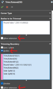
- For the “Trimming Boundary” section, the tubes that are used to trim the other bodies is infinitely extended, this is almost always useless/bad in our case
“Allow Extension” is fairly self-explanatory. For “Bodies to be Trimmed”, the tube that will be trimmed is extended to meet the other tubes that are the trimming boundary (rarely needed)

I.E. The left is a good case with “Allow Extension” turned off, the right is bad and will cause many issues later on ( I will talk about zero-thickness geometry later )
Interference Detection:

Before moving to Ansys Workbench/SolidWorks simming, MAKE SURE to utilize the interference tool as it ensures that tubes are not intersecting each other (i.e. the tubes are properly trimmed and connected)
- If there are interferences, that most likely means you failed to select a trimming boundary tube
- Additionally, interference detection will show you every place where interference is detected, so that means you should go to that specific trim and see if you are missing anything
Zero Thickness Geometry:
- Zero thickness geometry occurs when there is a gap between tubes, most likely caused by improper trimming/connecting tubing
To fix this, ensure that “Allow Extension” is turned off for the trimming boundary, which makes sure that the tube that is trimmed is not overcut.
- Lastly, when finished with the frame design, combine the frame into one body with the combine tool, and export your .sldprt file as a parasolid (.x_t) as this preserves the geometry better when transferring to Ansys Mechanical
How to FEA (Specifically in Ansys Mechanical)

As a frame member, you will begin to have a love-hate relationship with Ansys Mechanical. Ansys Mechanical is a finite element analysis software which just simply means that it can simulate different effects like forces, heat, flow, vibrations, etc. of a given part. It does this by taking in the hundreds of thousands and millions of mathematical and physics-based equations to quantify these effects and help give data on the design and production of a given part. You will have a love-hate relationship with Ansys because though it is useful, it is also painfully slow and unoptimized for the sheer intensity and volume from our frame files (I will get into the specifics later on but just know, frames hold a lot of tubes and data points, more data points = more run time = more sadness).
How to start a simulation

- After opening Ansys Mechanical, create a Static Structural project, and import your parasolid (.x_t) file into the geometry slot.
- Next, open the model and wait for Ansys Mechanical to launch.
- When you get into Ansys Mechanical, ensure that your geometry has the proper material applied (this affects yield and ultimate strength, force propagation, and essentially all your results)
Meshing
- Now when it comes to meshing in Ansys, this is really a key feature where Ansys shines above standard SolidWorks FEA, in terms of the vast amount of settings and tweakable options available to you for quality mesh refinement. However, having all these options means that if you don’t know how to use them properly, you can run into a lot of headaches.
- That being said, typically using a 3mm automatically generated mesh can give you decent results, although if you know how to/want to get the best, most accurate results, please look deeper into sweep meshing, tetrahedral meshing, etc.
- IK this section is pretty lacking, that is solely because as of writing this, I do not have enough experience to confidently lead any reader in the right direction myself. However, anything is possible with enough research and practice, so I encourage you to get out there and start meshing :D
- This is an excellent resource made by the now LHR Combustion Body Lead, Ryan Gretta
Supports
- Supports are pretty easy to grasp IMO, basically what they do is properly hold your geometry so that when you simulate a load case, it doesn’t just move and take 0 force. Supports make your simulations realistic.
- That being said, we typically opt for a type of fixed support, specifically located in 4 areas of the car that mimic the tire contact patches
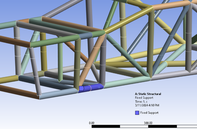

In my experience, I’ve found the supports used in the bottom picture (remote displacement) as opposed to the top (fixed supports) to be more accurate and useful for results because:
- A fixed support makes it so the selected bodies do not deform or move. This is not optimal because the actual frame WILL deform, which makes these results partially inaccurate. Hence, a displacement or remote displacement will accurately represent the deformation of the frame tubing, as well as properly propagate the forces throughout the selected tube.
- Additionally, a remote displacement allows you to utilize a specific coordinate to represent where the forces/deformation should propagate. In this case, though we selected the bottom suspension box tubing, the remote displacement mimics the location of the actual tire contact patch, which is more accurate to where the actual load case of a crash would propagate.
Otherwise, supports are pretty simple, just support the four tire contact patch locations, and you are good to go.
Forces/Load Cases

- Again this is fairly simple, all you need to do is apply a force at the specific place the ASC guidelines want it applied. The only “hard” part of this process is understanding the actual amounts of force you should be applying.
- For instance, a “5g” load case does not just mean five times the force of gravity on the frame, but rather five times the force of gravity relative to the weight of the entire car. This means you need a mass in kg, multiply by 9.81 (gravitational constant), and then multiply by 5.
- Additionally, when a load case has multiple components, make sure that your force in Ansys is “defined by” components, not vectors.
- Lastly, if a load case is at an angle, for example, 30 degrees from the horizontal, all this requires is the use of simple cos and sin functions. Pretty straight forward
Solution and getting your sim results
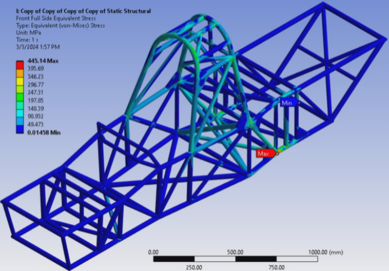
- Now all that’s left to do is add your solution result plots and run the simulation.
- Per ASC guidelines, you need to have the following solutions when you screenshot/document your passing sim results:
- Equivalent (von-mises) stress
- Maximum principal stress
- Displacement
- Factor of Safety (this does not need to be documented but it makes analyzing your results a lot easier)
- Now when viewing your results, keep these in mind when checking if your design is successful/validated and passing:
- When viewing the occupant cell sims, does the frame displace more than 25mm? Is the equivalent or maximum principal stress over the ultimate tensile strength of the material? Is the factor of safety ever below 1? If yes to any, you have failed these sims.
- When viewing roll cage sims, does the frame have eq or max principal stress over the yield strength (in the roll cage, anywhere above the rest of the chassis) or the ultimate strength (anywhere below the roll cage)? Is the factor of safety ever below 1.1 (in the roll cage) or 1.0 (below the roll cage)? If yes to any, you have failed these sims.
- Otherwise, if you pass the sims for every load case, your frame is finished, simulated, and validated. 👍
What to do if you fail
If you end up failing a load case, it’s back to the drawing board with your design.
When you end up changing your design to try again, it is best to analyze ALL LOAD CASES, and not just the one you are failing as changes in design AFFECT. EVERY. LOAD CASE.
- This sucks but it is the harsh reality, design changes can critically affect every load case and component of the car, so change designs strategically and cautiously
- This is why I gave you materials, solids, statics, and structural knowledge beforehand, so your changes are more educated decisions and not guesses
Making changes to the car can be as easy as changing the outer diameter or wall thickness of a tube
- Deciding between the two should be based on the stiffness (inertia) to weight ratio of the tubing. The overall goal of the car is to be as stiff as possible with the least amount of weight, therefore you want the greatest gain in stiffness with the smallest change in weight
- Additionally, a change like this should only be made if the load pathing of the structure is wrong or inoptimal.

On the other hand, if your load pathing needs to be changed, this is where cross bracing should be added/moved/removed altogether. Again, keep weight in mind, sometimes adding the biggest and strongest cross bracing can be overkill and just add unneeded weight.
Just keep in mind that frame design is an iterative process. Creating a successful design is completely different from creating an optimized design, as you can have a successful, passing design, without it being optimized for weight, stiffness, etc. This means you may have to run tens of hundreds of sims, you may have to stare at your design and try many different remedies to solve your problem. It all depends on the goal of the lead, the subsystem, and the team as a whole.
VR3 Ordering
- As mentioned before, VR3 is our place for mitering and acquiring all tubing. That being said, I won’t go into much detail, as they have everything documented themselves. Follow their guides and you will be fine, they are very accommodating and friendly.
Frame Jigging
- In short, a frame jig is essentially an assembly of parts that properly support the tubing/suspension tabs/any welded part during the welding process.
- A lot of the writing composed in this section is from some of the lovely Combustion and Election members who have helped guide and educate me and my members on the jigging process.
How to design a frame jig
“Table flush jigs" or “frame hockey pucks” are cylindrical stock that we turn down and then have a hole in the middle to go into the optical table.
- These support the entire bottom level of the frame, which is the most critical part in welding the frame (i.e. if you start badly from the base, the entire frame will be bad, so support the bottom well and you will have better results overall)
After we fully weld the frame, we do the hardpoints (suspension tabs, ergo tabs, etc.) to mitigate warping from the welding. When welding/jigging, you need to have a planned order -> table flush (bottom layer) to the 2nd and potentially 3rd level, roll hoops, everything else (cross-braces) building up
Making your frame is fundamentally an exercise in precision locating and weldment construction, your main considerations should be datums (a fixed starting point) and stiffness. The optical table is your only reference for both geometric and positional tolerances, ergo, every critical jig you make should reference something about the optical table or something about a tube that is located off of the optical table. There are three main frame categories, critical external, critical internal, and non-critical.
- Critical external features are parts of your frame that drive car parameters decoupled from the rest of the frame (hardpoints, roll hoops, headrest supports, etc.
- Critical internal features are parts of your frame that only rely on internal geometry (steering column, rear box, etc.) These features of course will matter externally, but it’s more important to locate them to critical mating components, which if done correctly will satisfy external constraints.
- Non-critical features are tubes that don’t matter and are only there to provide structure to your frame, these are your buffers that take up tolerance stacks as they propagate through your frame and are there to support your critical features when the jigs are gone. These are the only tubes in your frame where you should be filling gaps, in an ideal world.
When creating your jig, think about 2 main things constraints in 3D space, and the purpose of your jig. Something is fully constrained if all 6 DOF (degrees of freedom, X, Y, Z, roll, pitch, yaw) have an external reaction by something you consider stiff enough to judge as infinitely stiff. The purpose of your jig is to hold geometry where you want it just long enough until the structure of your frame can hold it there on its own.
- The optical table is great for constraining DOFs, place a tube on the optical table and clamp it down, all 6 DOFs are fully constrained through friction and interference with the table and clamp with a jig stiffness you can approximate as infinity.
- With a flat bottom frame or a frame with parallel bottom shelves, fully constraining your frame is as simple as designing a jig that uses the optical table surface as a geometric reference and the holes as a positional reference. The “puck method” with precision shoulder bolts and strap/toe clamps, is the best way to do this.
- Moving up your frame is where things start getting tricky. Your priority is to constrain all 6 DOFs of every critical external feature on your frame to form a basis for your critical internal and non-critical pieces. The challenge is designing a jig that is simple to make and install precisely while being stiff enough to fully constrain your frame even after weld distortion becomes a factor.
- Remember the purpose of a jig, if your jig is designed in such a way that your welder has no access to create the joints that would allow you to take the jig off, your design is doing more harm than good and has failed its task.
- Assuming you have created a jig for your critical external features with correct geometric tolerancing, positional tolerancing, adequate stiffness, and torch access, the next thing to consider is the dynamics of the joining process. Anytime you strike an arc, create a weld pool, and end the weld, your parts cool an extremely fast rate in the open air. Your main concerns are martensitic formation (Deformed shape) and weld distortion.
- When you heat the metal past its Austenic temperature and rapidly cool, you are susceptible to forming martensite, an extremely hard and brittle phase that can lead to catastrophic failure when a critical load is applied. You cannot avoid going past the Austenitic temperature to get a proper fusion joint.
- The primary source of heat transfer when you weld is conduction (heat is transferred from the hotter end to the colder end of an object). The base metal and anything connected will conduct heat away from your weld and form different regions including the HAZ (heat-affected zone). This is where you are most likely to see distortion in your parts as the weld cools. You also need to consider how your jig will respond to the heat, aluminum has a thermal expansion coefficient of ~twice that of steel; if you make your jig out of aluminum it may move significantly when exposed to the heat of your weld through conduction.
- With these two things in mind, you can start to problem-solve and compromise. Think about what you can control, the big two are the design of your jig and convective heat transfer.
- You can be smart about how you design your jig in this regard, the first thing that comes to my mind is ceramic heat isolation spacers for the connection between your features and your jig. They are very stiff and highly insulating. You can also preheat your parts before welding to "even out" the heat curve inside your material.
- You can also be smart about your weld process and post-weld treatment. You want to reduce the chance of martensite in areas of your frame that will see the most stress. Martensite is formed when you cool your joint at a fast rate and dependent on your material selection, assuming your material selection is locked in, your only option is to increase the time it takes for the weld to cool. This is easy to do with something like weld blankets, or the ceramic spacers above.
- Perhaps the easiest way to help with both of these things is to weld in small sessions jumping around the frame to let your welds cool slowly with as small a HAZ as possible while still being time-efficient.
- With all of this in mind, be creative with how you decide to jig things, your jig alone does not need to precisely locate a critical component. If your jig can substantially hold your part and you can position it with something else, that is fine
- A great example of this is the plumb bob (a pointed weight attached to the end of the string and is used to find a vertical reference line called plumb) on your roll hoop. Attach a plumb bob tangent to the top of your roll hoop in the center, and mark on your optical table the theoretical perfect point that would connect an orthogonal line between the plane of your optical table and the tangent line to the cross-section of your roll hoop, assuming your table is level and orthogonal to the gravity vector, and the bottom of your roll hoop can be datumed to your frame, this will fully constrain the position of the hoop.
- Once your critical external features are fully constrained, you can move on to critical internal, using the external as a reference.
- Make simple jigs that restrict all 6 DOFs and prioritize accessibility, these features most likely already have challenging access due to being inside of the frame.
- Make these as stiff as you reasonably can and heavily leverage your newfound knowledge of weld dynamics to get away with less-than-ideal jigs
Welding

Welding the frame and TIG welding in general is a meticulous process that requires lots of practice and experimentation to become comfortable with and effective at.
TIG welding stands for Tungsten Inert Gas Welding, which involves a Tungsten electrode that generates an arc to melt the metal while Argon gas is flowed around the arc to shield the welding area from airborne contaminants and oxidation.
Some Basics to start out:
- Polarity: This means whether you are running direct current (DC) or alternating current (AC). I won’t get into the nitty gritty but AC is used primarily for Aluminum, DC is used primarily for Steel.
- Pre and Post-flow: Pre-flow refers to the flow of gas before the arc to protect the weld area. Post-flow refers to the flow of gas after the arc is stopped, which keeps a gas flow going for a short amount of time after welding to further shield the area and let it cool before being exposed to the air.
- Keep your torch relatively at a 45-60 degree angle, not only to make a good path for your arc and heat-affected zone, but also help filler placement be perpendicular to the tungsten rod.
Step-by-step guide
Related articles