Acceptable Formats
The Epilog Fusion Pro 48 has a bed size of 48" x 36" and can accommodate a full sheet of chip board from the Co-Op.
The laser cutter can cut vector lines from Rhino 3D, AutoCAD, or Adobe Illustrator. With any option, the main purpose in file preparation is to separate your line work based on the different power levels and order in which you want to cut your material. The specific power-parameters and order of the cuts are handled from within the Epilog Dashboard.
All linework must be on the same 0 Z plane.
Rhino Guide
- Prepare your line work at full-scale, then scale down to your desired scale-cut size within your file
- This must be done within Rhino before you send the file to the Laser Cutter
- Separate your line work in to distinct layers according to the desired power levels and order of cuts. In the Layers tab, assign each of these new layers their own unique color from this list of options:
- Black
- Red
- Orange
- Yellow
- Green
- Cyan
- Blue
- Magenta
- Drag-select all of the line work, and navigate to the Properties tab. Make sure that Display Color, Linetype, Print Color, and Print Width are all set to By Layer.
- Lastly, with all of the line work selected, type in the command "SetPt" – in the pop-up, uncheck the boxes next to Set X and Set Y, and make sure that Align to World is selected. After hitting OK, type in 0 to move all of your linework to Z = 0.
- When printing to the Epilog Dashboard, use the Window option under View and Output Scale in the print dialog.
- (Important) Make sure to set your Output Type is set to Vector Output
- You can now follow the steps from the How to Prepare the Laser Cutter page.

AutoCAD Guide
| Info | |||
|---|---|---|---|
|
Acceptable Formats
The Laser Cutter will cut from either AutoCAD (.dxf) or Adobe Illustrator, accommodating materials up to 18"x32".
...
The pre-configured template file has labeled cut order layers and a no-print boundary representing the space of the laser cutter bed. It is located on the desktop and is attached below. Please use this template for all files.
Laser Cutter.ctb (Start Menu → Run → %USERPROFILE%\AppData\Roaming\Autodesk\AutoCAD 2019\R23.0\enu\Plotters\Plot Styles - this is the directory on the laser cutter computer where you copy the file.)
Instructions:
Material Test for AutoCAD - Epilog
Instructions
- Prepare your linework at full-scale, then scale down to your desired scale-cut size.
- Separate your linework into distinct layers according to the different power levels for the cuts. In the Layers tab, assign each of these new layers their own unique color from this list of options:
- Black
- Red
- Orange
- Yellow
- Green
- Cyan
- Blue
- Magenta
- Ensure
- Open your AutoCAD file and select all lines you wish to cut. Paste them into the template using Ctrl+C and Ctrl+V, NOT the CO copy command.
- Under properties (when an element is selected, right click and select "Properties"), ensure that all geometries are set to "By Layer" in in the color, linetypeline type, line weight, and transparency drop downs-down menus.If you imported your file from Illustrator, you will need to take extra steps (although these are helpful tips for AutoCAD generated files as well):
- Run the overkill command to ensure there are no overlapping
- Select all the geometry produced by Illustrator and enter command EXPLODE. Do this twice to ensure that the geometries ungroup (you should see a prompt reading "Cannot explode Spline" at the completion of the second explode)
- Enter command PEDIT, enter M for multiple, and select your geometries (if you have a lot of lines or they are complicated, it may be best to do this step in smaller groups). Enter Y to convert lines to polylines. Hit enter again (the default precision is fine). Enter J to join and hit enter twice to exit the command. If your file has complicated geometries, it is a good idea to run the PEDIT command sequence twice. Enter OVERKILL to remove duplicate lines (to prevent the laser cutter from cutting over lines twice or cutting slower). Or, from the menu select Express --> Modify --> Delete Duplicate
- Set the cut order/color assignments of the geometries. TIP: It is best to etch first, then cut geometries inside others, and then geometries that lie outside others can be cut (ex: in an elevation of a brick wall with a window, etch the bricks first, cut the window second, then cut out the whole wall). This prevents pieces from moving and cutting incorrectly.
- The order is as follows:
- black (AutCAD index color #7) - this is a no-cut layer
- red (AutCAD index color #1)
- green (AutCAD index color #3)
- yellow (AutCAD index color #2)
- blue (AutCAD index color #5)
- magenta (AutCAD index color #6)
- cyan (AutCAD index color #4)
- orange (AutCAD index color #40)
- Your file is now ready to cut!
2-Preparing Illustrator Files
...
- You can now follow the steps from the How to Prepare the Laser Cutter page.
Illustrator Guide
Instructions
- All vector lines and shapes (even if filled) must have a line weight of 0.001
...
- in order to be recognized by the laser cutter. The lines you intend to engrave can be either 1.0 or 0.1.
Note: This does make the lines very difficult to see, so this is usually done as the last step before cutting. - Line and fill colors must be assigned using RGB values and must conform to the following, or else they will not be recognized

...
- . Again, this is to set the order and type (cut or etch) of line

...
...
...
...
...
- When you first open the file, go to File>Document Color Mode>RGB. You can create swatches of the RGB colors above.
...
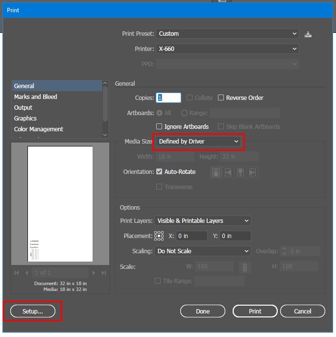
- When defining the settings, leave the Media: Size as "Defined by Driver."
- When your file is ready to cut,
...
- go to File>Print. To select cut/etch settings click the "Setup..." button (bottom left corner of the dialog box).
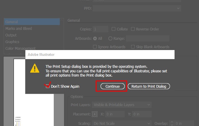
At the warning screen, click "Continue."
In the white Print dialog box, select "Preferences."

Within this dialog box you can create/edit/save your settings.

Click "OK" > "Print" > "Print", Then run the laser cutter.
Notes:
- If you want to cut dashed lines, you must use RAST as the pen mode in the Printing Preferences dialog.
- If you are laser cutting text, select the text, right-click > Create Outlines. Then inverse the fill/outline and double check your stroke is set to .001
3- Preparing Topos/Maps
There are many ways to cut your contour map, here is one way we found to be efficient and may reduce mistakes.
- You can now follow the steps from the How to Prepare the Laser Cutter page.
| Page properties | ||||||
|---|---|---|---|---|---|---|
| ||||||
|
...